
High-pressure shutdown
Shut down when tubing or casing pressure exceeds your set limit.
Connect your PCP’s drive and wellhead pressures to Amplified. Monitor the pump, act on alarms, and control it remotely.
Dedicated tubing and casing pressure sensors complete the picture, bringing wellhead pressure, pump performance, and remote control into one platform.
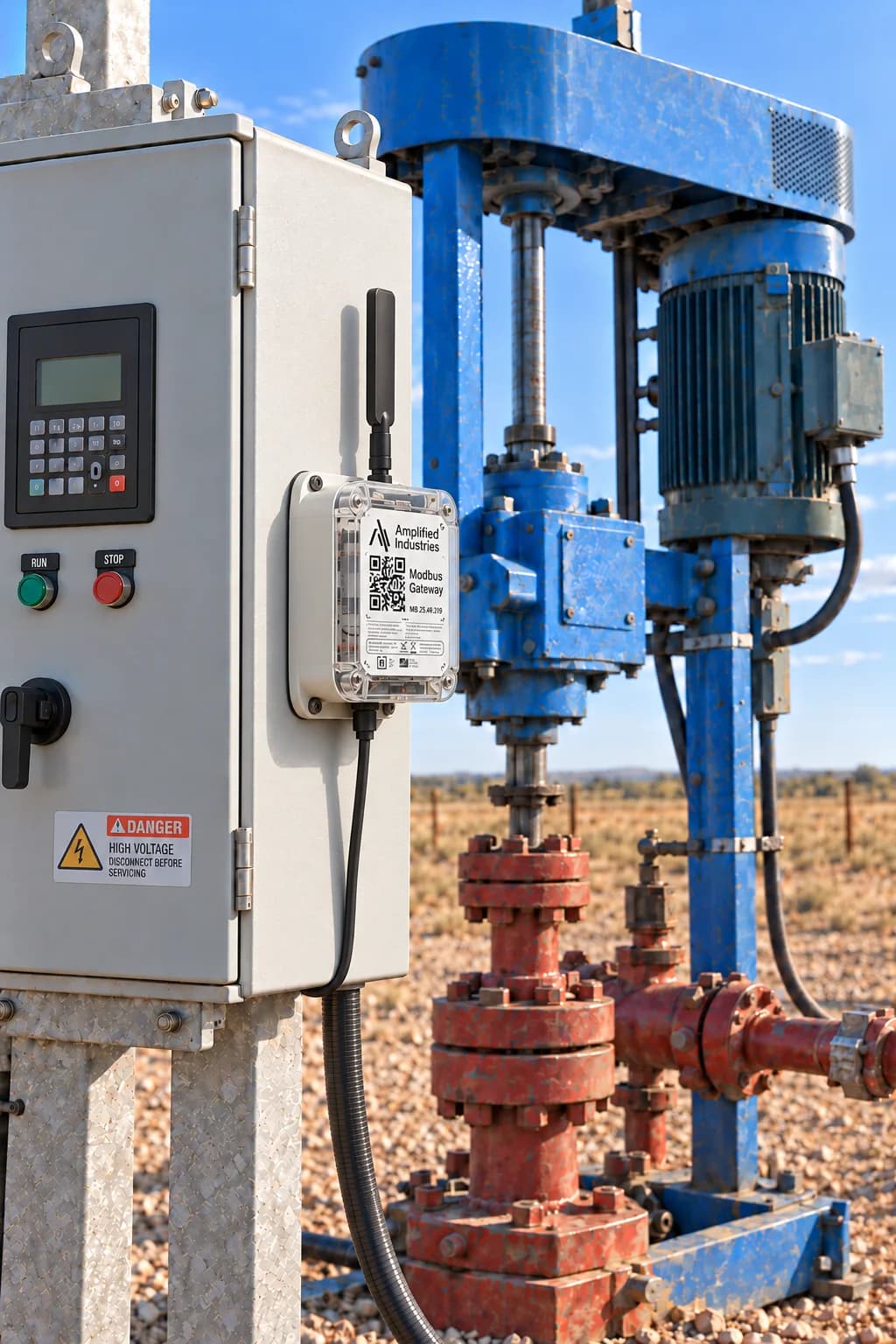
Relay or Modbus
Two ways to control the pump
Tubing & casing
Pressure on both sides of the well
App, SMS, or call
Runaway, inactive, and pressure alarms
Connect your existing drive controller via Modbus, or use our relay to control the pump.
01 / Relay control
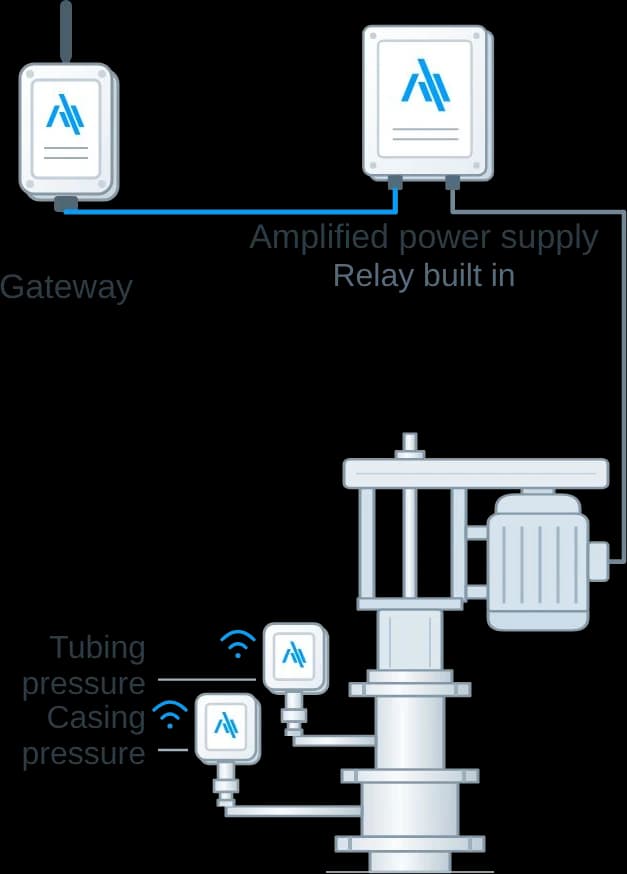
A gateway and the Amplified power supply, with the relay built in, start and stop the pump and run it on timers. Two wireless pressure devices read tubing and casing.
Gateway + Amplified power supply + pressure devices
02 / Modbus control
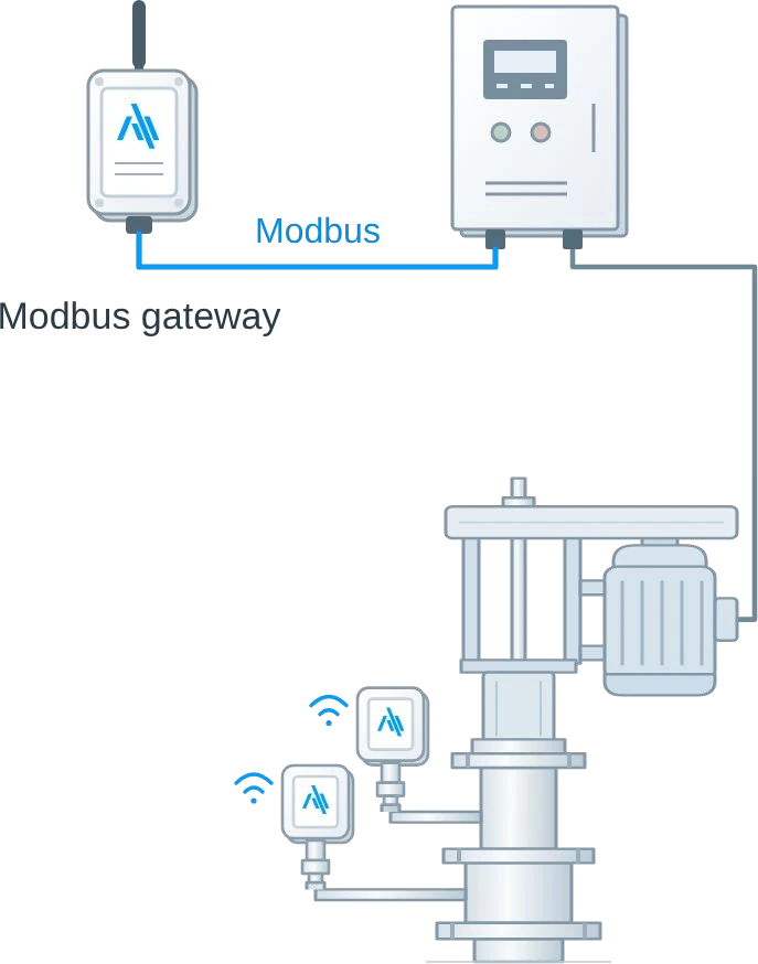
A Modbus gateway reads the drive you already have and passes commands back to it, so you can start, stop, and adjust speed from the dashboard. The same pressure devices complete the well.
Modbus gateway + your drive + pressure devices
Continuous wellhead and drive measurements, with an operating history your whole team can use.
Two dedicated pressure devices capture both sides of the well.
See when the pump is running, when it stops, and how the motor is loaded.
Read torque, RPM, frequency, voltage, and flow from a compatible Modbus drive.
Add Amplified tank products to follow daily production alongside pump performance.
* On Modbus drives.
Pressure and motor current on one shared time axis. When the pump stops, you see it in the current and in how tubing and casing pressure respond, and again when it comes back.
Illustrative data modelled on a PCP well, not a recording.
| Time | Tubing (psi) | Casing (psi) | Motor current (A) |
|---|---|---|---|
| 18:00 | 67 | 31 | 55 |
| 19:00 | 66 | 31 | 56 |
| 20:00 | 67 | 31 | 55 |
| 21:00 | 66 | 31 | 54 |
| 22:00 | 67 | 31 | 54 |
| 23:00 | 66 | 31 | 55 |
| 00:00 | 67 | 31 | 56 |
| 01:00 | 66 | 31 | 55 |
| 02:00 | 67 | 31 | 56 |
| 03:00 | 67 | 31 | 0 |
| 04:00 | 44 | 34 | 0 |
| 05:00 | 45 | 36 | 0 |
| 06:00 | 59 | 34 | 55 |
| 07:00 | 65 | 32 | 55 |
| 08:00 | 65 | 32 | 55 |
| 09:00 | 65 | 31 | 54 |
| 10:00 | 67 | 31 | 56 |
| 11:00 | 67 | 31 | 56 |
| 12:00 | 65 | 31 | 55 |
| 13:00 | 67 | 31 | 54 |
| 14:00 | 66 | 31 | 54 |
| 15:00 | 67 | 31 | 54 |
| 16:00 | 66 | 31 | 56 |
| 17:00 | 65 | 31 | 56 |
| 18:00 | 65 | 31 | 54 |
Start or stop the PCP, set run timers, and adjust drive speed from the same dashboard you use to monitor the well.
Start and stop the pump from the dashboard or app. Set run timers with the relay kit.
On a Modbus drive, change the frequency setpoint without a trip to the panel.
Runaway, inactive, and pressure alarms by app, SMS, or call, with tickets to track your team’s response.
Pump settings
Next 4 hours
On Modbus drives
Shut down when tubing or casing pressure exceeds your set limit.
Stop on low torque when dry running is suspected. You set the limit.
Your PCP wells connect to the full Amplified system, in the same dashboard and app as the rest of your field. Manage PCPs, rod pumps, gas lift, tanks, and compressors together, with a shared view of the whole operation.
Connect Amplified tank-level alarms to automatic well shutoff to help prevent overflows. Pump performance, tank levels, and daily production reports stay together.
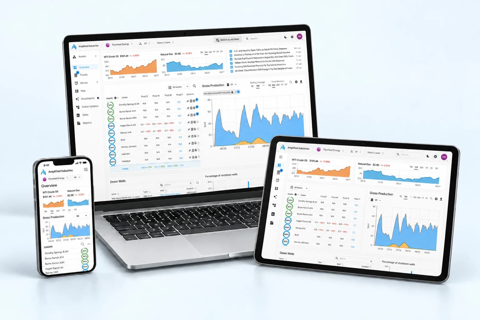
Tell us about your drives and we’ll recommend the relay or Modbus kit for each well.
Every card of every stroke, downhole cards derived from surface data, and control that changes what the well is doing.
Real-time ultra-high-resolution data on your ESP, alarms, and control—all on the same platform as the rest of your field.
Automatic gas lift optimization with remote injection control, continuous and intermittent operation, and valve diagnostics all connected to measured production.
Remote control, high-frequency pressure data, and automatic optimization for plunger lift wells using whatever you already have on site.